
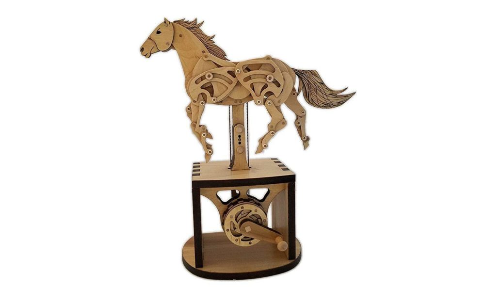
When I first thought of my idea, I had planned to make a mechanical buffalo running similar to the photo above. My plan for fabrication was to laser cut all of the parts out of 1/8″ plywood. Since I pivoted from this initial idea, I was able to take advantage of having a 3D printer in my room and design a product that was able to be easily 3D printed, as seen below.
![]()
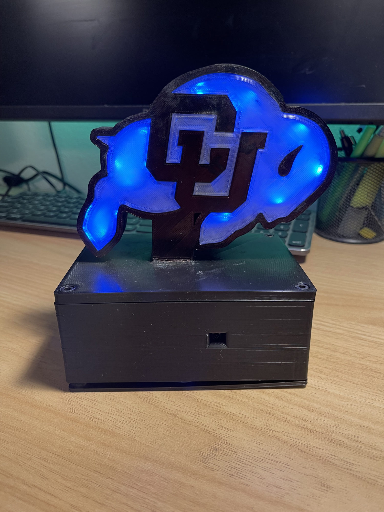
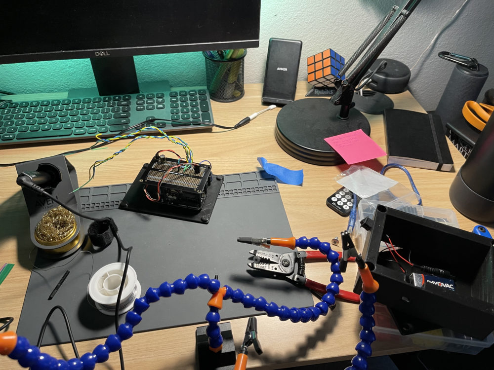
The design I ended up on for my first iteration started with the black CU Buffalo front plate, which was the main part of the design. From there, I had a clear face plate on both sides of the CU buffalo face plate that slipped into place and glued in to help diffuse the color from the LED lights. From there, I designed a top plate that was glued to the CU Buffalo front plate in order to make sure the front plate was perpendicular to the whole design and then fastened to the middle piece with screws. The middle piece featured an opening and cut-out for the IR sensor, along with toleranced openings for threaded inserts that would help keep the top plate fastened down. Another goal and specification that I added last minute were to be able to change the electronics and code easily without having to take anything apart. My plan to accomplish this goal was to create a separate bottom plate that I could print first and mount all of the electronics and be able to test with it extensively, as you can see in the photo below.
For manufacturing, I was fortunate enough that I ![]() had a 3D printer at home, so I was able to skip all of the lines in the ITLL and Idea Forge. I started with printing all of the PLA parts firsts since I was most familiar and experienced with it. Most of the PLA parts went according to plan except for the CU Buffalo black faceplate, as I first printed it with a Raft, which left a sharp edge. I then printed it again and put in the LEDs and realized that the CU logo was full, so there was no light getting through each of the pieces, so I redesigned the CU Buffalo faceplate to feature slots so the light could travel through the whole piece and not be blocked. Since most of the parts when to plan, I was able to print all of the PLA parts in 2-3 days. From there, I was able to experiment with printing with clear TPU since I have had the filament for a long time but have never used it. After using it, it is actually way easier to use than some YouTube channels and review sites have framed it, as I never really had a problem after I set my settings.
had a 3D printer at home, so I was able to skip all of the lines in the ITLL and Idea Forge. I started with printing all of the PLA parts firsts since I was most familiar and experienced with it. Most of the PLA parts went according to plan except for the CU Buffalo black faceplate, as I first printed it with a Raft, which left a sharp edge. I then printed it again and put in the LEDs and realized that the CU logo was full, so there was no light getting through each of the pieces, so I redesigned the CU Buffalo faceplate to feature slots so the light could travel through the whole piece and not be blocked. Since most of the parts when to plan, I was able to print all of the PLA parts in 2-3 days. From there, I was able to experiment with printing with clear TPU since I have had the filament for a long time but have never used it. After using it, it is actually way easier to use than some YouTube channels and review sites have framed it, as I never really had a problem after I set my settings.
After printing all of the parts, I then started to assemble them all together, starting with the CU Buffalo Black faceplate to the top plate. Next, I pressed fit one of the transparent faceplates and the LED strips right next to it. I then glued threaded inserts into the middle cover to fasten down the top plate. I next wired all of the LED wires to the electronics board and started to debug and code.

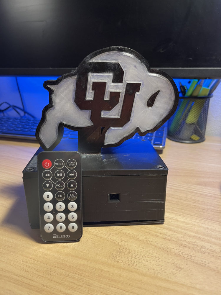
With my code, I used a switch statement that initially took the input from the IR remote as a hex number and compared it to values that I had noted before for buttons on the certain remote I was going to use. So If the IR receiver detects an IR signal, it then checks the values from that signal and changes the lights accordingly. The current lighting setup that I have programmed is a solid Red, Blue, Green, and White, along with a fade setting between red, blue, and white and a rotating color scheme that rotates along the whole outer perimeter of the buffalo.
CAD Files:
Presentation: