
In terms of progress on my upcycling project I have decided on my design, material choice and begun creating a 3D model which I will go into in more detail below.
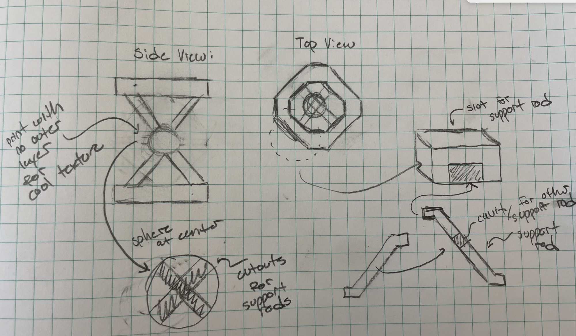
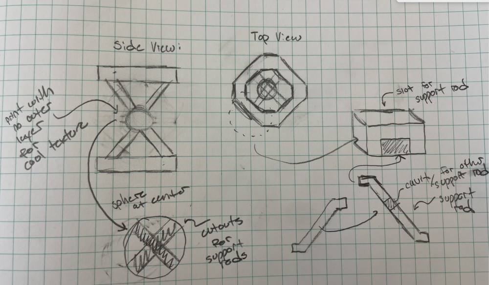
Below in Figure 1 is a sketch of my design breaking it down into its 6 components. As can be seen in the side view, the overall figure resembles the shape of a classic hour glass. The structure will sit on a hexagonal base plate, with an identical one placed at the top. Two diagonal support rods will separate these plates and a two part sphere will sit in the middle, providing both structural support and acting at the “center piece.” The sphere will be printed with no outer layer, exposing an intricate fill pattern which I will elaborate more on below. Using the concept of Miyadaiku, my aesthetic, there will be no fasteners connecting the parts. Instead, there will be slot cutout and accompanying “male” feature to fit within. These cutouts can be found in the top and bottom plates and the sphere and the “male” features are on the support rods.
While I had initially thought to use either wood or cardboard to as the material, I will instead opt to use scrap filament to make these parts. This will involve upcycling because I will make use of almost empty filament rolls that would otherwise be trash. By manually spicing them together, I will make frankenstein-esc components. I decided to use filament because I am worried about the precision necessary with wood working and my lack of prior experience. With printing on the other hand, I will be able to quickly iterate as necessary. After making adequate prints, I will sand down all of the components to create a more finished look and then potentially paint them to further extend the finished look.
My next step will be to convert this drawing into part files in solidworks. I will begin by making the entire structure in one part and then use plane cuts to separate the structure in the the individual components. I will then make an instal print and then decide on the final size and tolerances so that the parts fit together. Moving forward, I am excited to being making the final design and being to see it materialize.
2 Comments. Leave new
Hey Max,
Your plan seems pretty good and I can relate to wanting to change to filament because I also have no experience with woodworking but a lot of experience with 3D printing. I am excited to see how it comes out with the final product. Will you be using FDM printing or some sort of resign printer?
Hi David, thank you for reading my post! I will be using FDM printers so that I can use all the excess spools!