
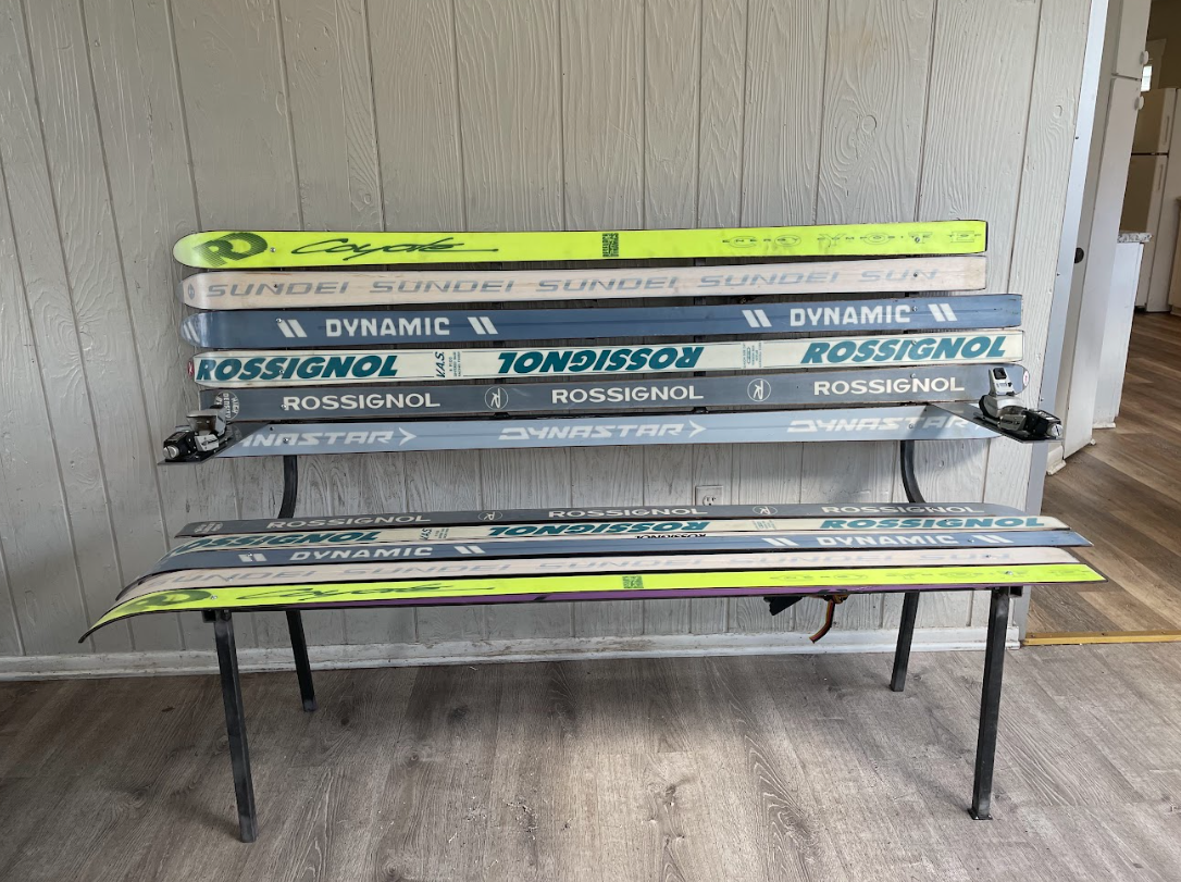
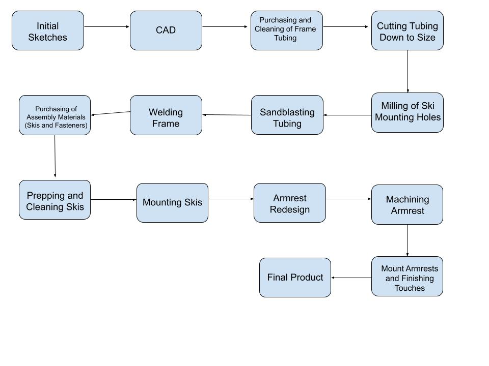
For my final project I created a ski bench with vintage skis in the aesthetic of Retro Skiing. In this post I will document my fabrication process, from initial sketches to final adjustments. This process started after I realized my inspiration and landed on my aesthetic. This inspiration and aesthetic allowed me sketch my initial plans for my project, and start the design process. In my initial project report, I outlined a timeline of things that needed to be done. This progress flowchart was generally followed throughout the process, but several steps were moved around. Below I have created a flowchart for my actual design process that I followed which will help better visualize the process.
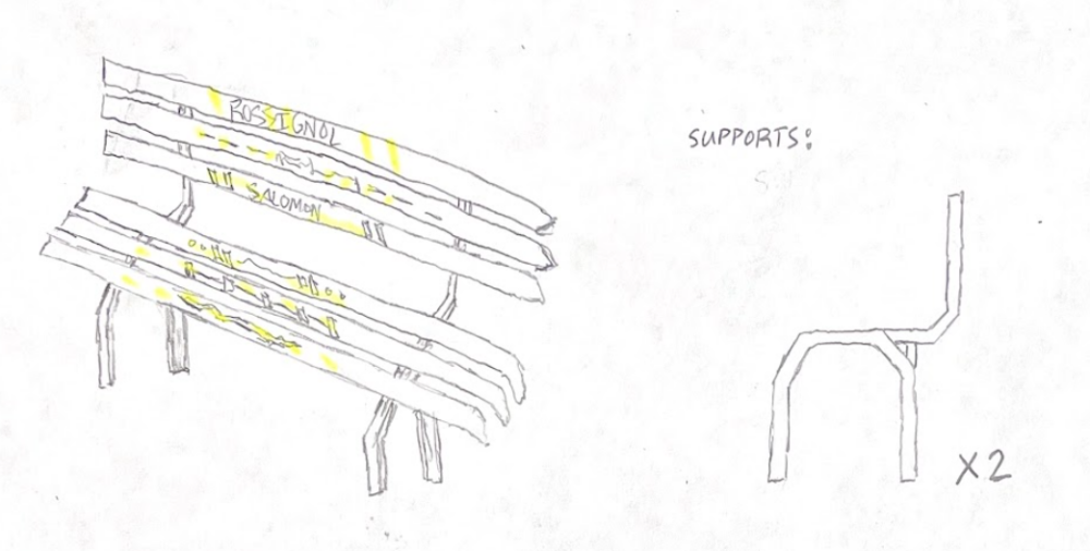
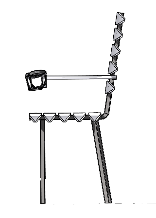
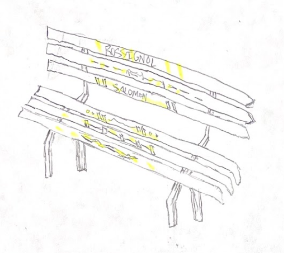
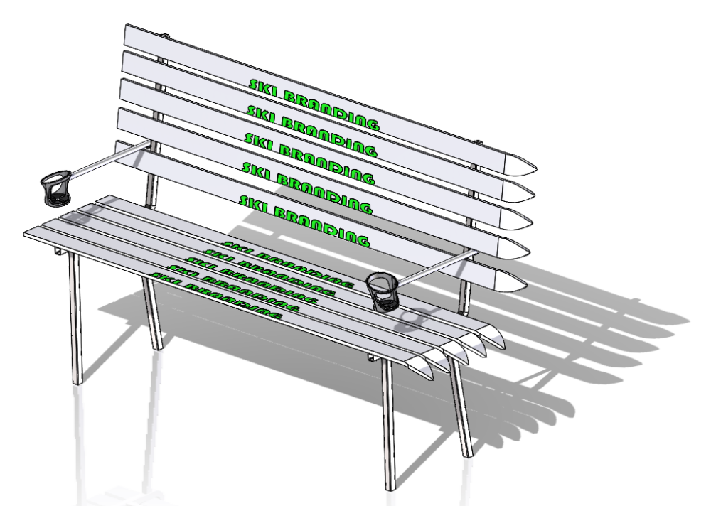
The design process started with turning my initial ideas, inspiration, and aesthetic, into a rough initial sketch. These sketches were similar to the final CAD, and final product, however changed slightly as I progressed through the design process. These initial sketches were very rudimentary and did not take any structural design into account. From this initial sketch I created the CAD for the project. I started this CAD by creating a mock ski part in SolidWorks. This part had the same average length and width of ski I was looking to purchase, and this part was crucial for dimensioning the rest of the bench. I then created a part for the stock tubing I was purchasing, and then made the frame parts by cutting and bending that stock tubing to my specifications. This is where I did have to take structural integrity and weight into consideration. The CAD design of the frame then flowed around the shape and dimensions of the ski CAD. I then created the dynamic arm rest and cupholder CAD, which would later change during the fabrication process.

After having done the initial CAD assembly and sitting on the design for several weeks, I knew it was time to start purchasing frame materials, which would make my project change from a concept to a physical thing. The purchasing of the frame materials made me rethink my initial CAD of the frame, so I after getting a quote for the overall weight of the steel tubing, I decided to tweak the frame design to make it more structurally sound. I initially omitted these extra supports, but after finding out that the weight was not as much as a initially thought, I decided to add them to prevent excessive deflection of the skis. After finalizing my frame design, I could confidently purchase the correct amount of steel tubing. I purchased this steel tubing from Metal Supermarkets in Golden, CO. I had the supplier cut several of the frame pieces to length before I picked them up, which later saved me time in the machine shop.
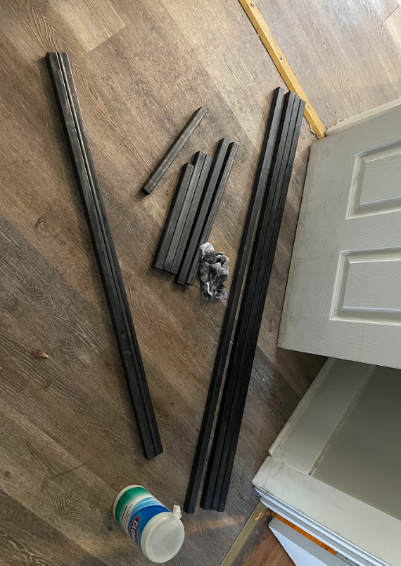
After picking up the metal tubing, I realized that the tubing was incredibly dirty covered in black suet, which would make the fabrication process very dirty and inconvenient, so my first step before the machine shop was wiping off all of the suet, from the stock tubing. I then took the tubing that needed to be altered to the machine shop, to start cutting segments down to length, before adding mounting holes and bending the correct components.
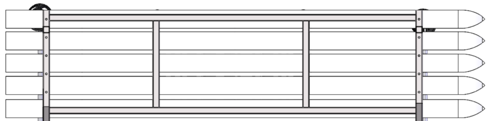
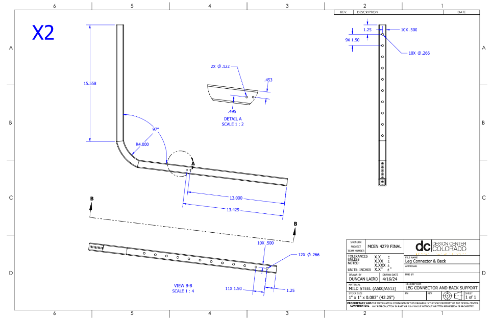
Before any machining could happen, I needed to create engineering drawings for each part of the tubing I was altering. These drawings needed to be checked by the engineers in the Idea Forge machine shop, before I could begin machining my parts. Below are some the two drawings I need for the metal tubing that was being altered.
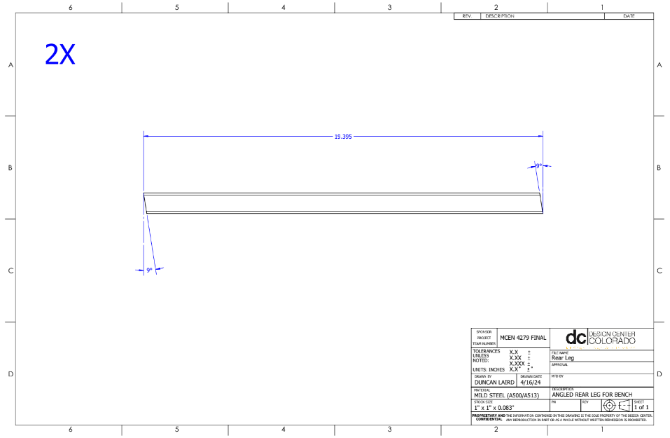
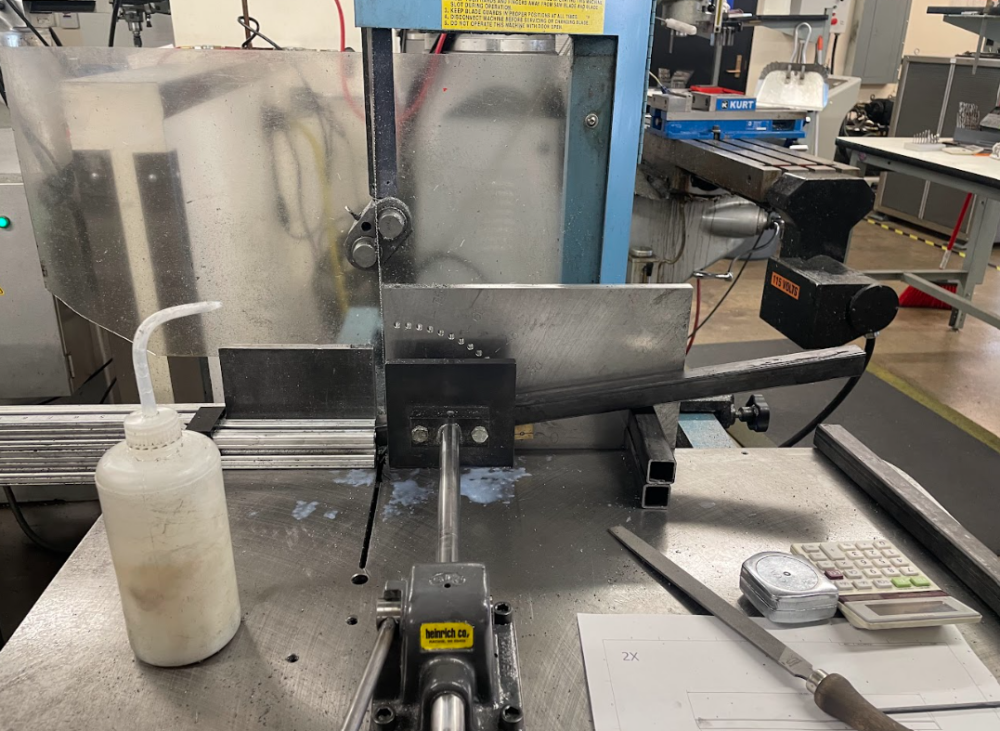
The first step in the machine shop was cutting the steel tubing to size. There were 4 pieces total that needed to be cut, which were the two seat and backing connectors, and the two angled back legs. The seat and backing connectors had to be cut down by 4 inches. I had to cut these segments down because when I ordered them from the metal supplier, I was unsure of their exact length, and ordered longer tubing than needed to be conservative in my material use. The second pair of segments that needed cutting were the angled back legs of the bench. These legs are angled to account for the people sitting on the bench adding weight to the back rest, and prevent tipping of the bench. I ordered these segments to the correct length, however, I needed to cut angles on each end of the segment. The angle I cut into each end of the segment was 9 degrees, shown in image 7. Throughout the cutting of these legs I doubled checked my measurements, and made sure they aligned with the height of the front legs.
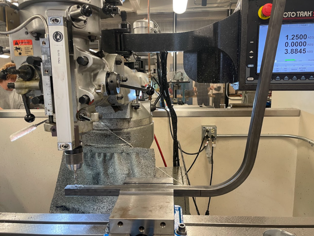
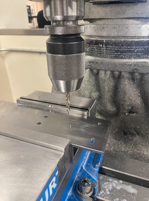
The second step in the machine shop was altering seat and back connector parts, adding the correct bend for the seat backing, and adding mounting holes for the fasteners to connect the skis. The first step in machining these parts was bending the angle in the tubing. Since I had never used the bending machine before, there was a learning process I had to complete first before using the machine. I used the bending machine in the Idea Forge machine shop to bend a 97 degree angle approximately 15.5 inches from the seat edge of the tubing. These angle was needed for ergonomic reasons, as this angle of back rest is much more comfortable than a 90 degree back rest. Once these angles were bent into the tubing, I milled 10 holes in the seating segment, and 12 holes in the backing segment. These holes were for mounting the skis to the frame, and since I had not purchased the skis yet, I evenly spaced the holes and drilled more than needed so I could be ready for any thickness and configuration of skis later on. I also milled 2 very small holes in the sides of these parts to mount the hinges for the cupholders, however these holes were not used later on.
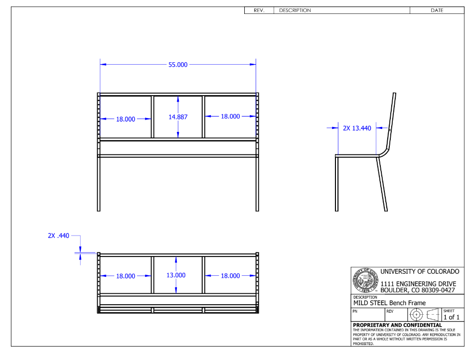
With all of the parts fully machined, I first checked my frame by laying it out on the floor to check that all dimensions were fitting properly. After seeing this layout work, I created a frame assembly drawing so I could accurately dimension the frame while welding. Another step I had to complete before welding, was sandblasting the areas of the metal tubing that would be welded. I used the sandblaster near the loading dock in the Idea Forge. The long crossbeam tubing segments were too large for the sandblaster, so I used the angle grinder to prepare those parts for welding.
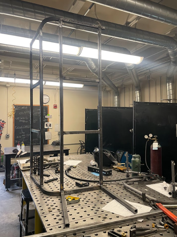
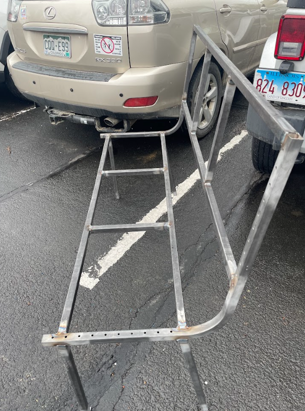
The welding went very smoothly and the final frame construction stood on its own perfectly. I had my friend help me with the welding so one of us could position and clamp down the parts while the other welded. The only issue that occurred during the welding process was that one of the front legs ended up being slightly shorter than the others, so I corrected this by welding on a thin slice of metal at the bottom of that leg, which made the bench perfectly even and not wobbly.
After the frame had been completely welded, it was time to add the skis. I purchased the skis from someone on Facebook market place, who had a collection of hundreds of vintage skis and he was selling them at a bulk price. I bought six pairs of skis from him, and he let me pick out whichever ones I wanted. I also purchased fasteners at Home Depot for all the components of the bench. These fasteners were higher quality and more uniform than the free ones at the Idea Forge. The next step was prepping the skis to be mounted, which included unscrewing the bindings and removing the brakes on the bindings that could not be removed. I then picked a ski design and order to put the skis in, and mounted the skis using 28 fasteners. I used 1/4-20 bolts and nuts on the underside of the bench.
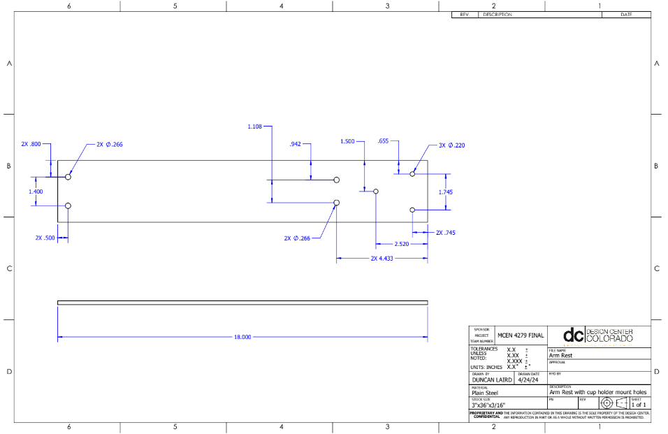
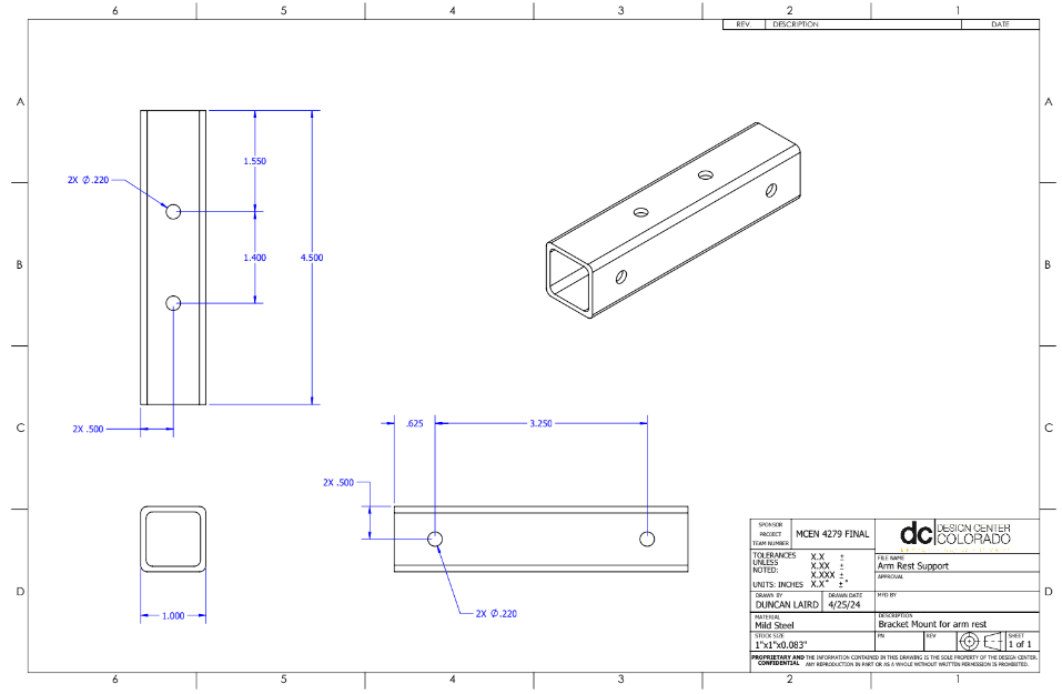
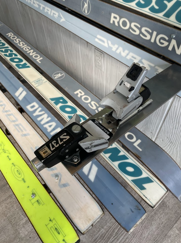
After removing all of the bindings from the skis, my roommate gave me an idea to use the excess bindings to make cup holders on the arm rests. This design deviates from my original cupholder design, but I really took a liking to the ski binding design, and the hinges I ordered for the other cup holder design were not large enough to support the bending moment on the end of the arm rest. After mocking the concept for the ski binding cup holders, I used a 36 inch sheet of steel I had from a previous project to mount the ski bindings, and created an engineering drawing for the arm rest to be machined. I also used excess square tubing I had leftover from the frame which I used to support the arm behind the bench backing.
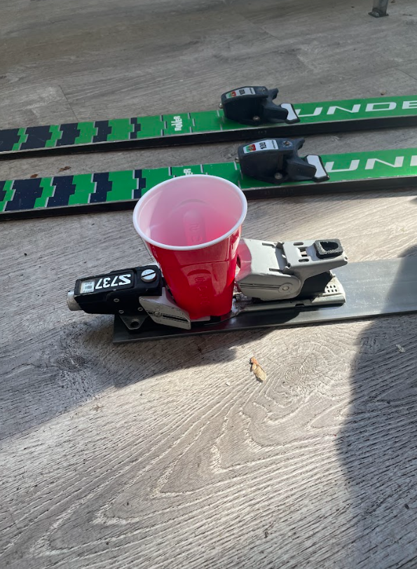
I really like how the final cupholder and armrest design came out. Even though they don’t pivot, I think they are much more aesthetically pleasing and structurally sound than the previous design. The arm rests also remain dynamic because the binding pieces are still able to clip in and be adjusted, which is a very cool and interactive way to hold your drink.
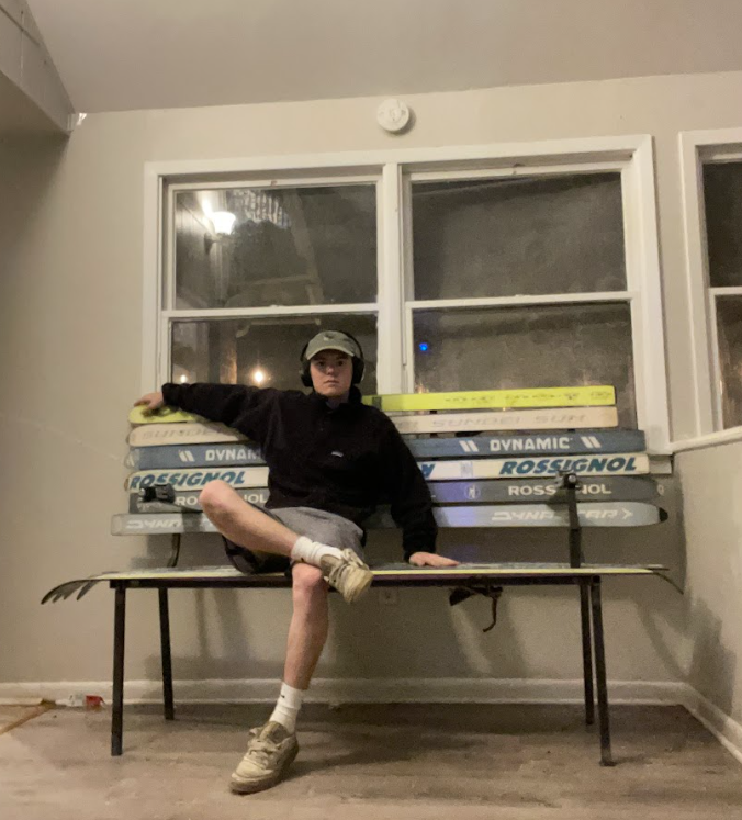
After mounting the armrests to the backing of the bench, the bench was officially complete and ready to be used. Below are some final images of the bench and the final cupholder design.
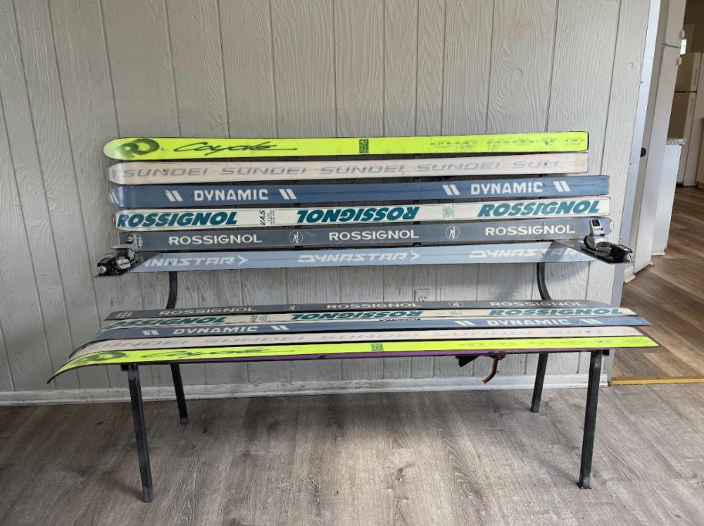
I am very pleased with the final design, aesthetic, and function of the final product. The only difference between the initial sketch, CAD, and the final design, are the cupholders and how they are mounted to the backing of the bench. Everything else in terms of function remained the same. Below are images from the three stages of the design process, showing minimal change across all steps of the process.
In term of the aesthetic, the colors of the bench slightly changed throughout the design process, which was due to the selection of the skis where I purchased them, but I kept with the retro colors, by including the neon greens and retro looking font designs on the bases of the skis. Overall the aesthetic remained the same and the final product embodies the Retro Ski aesthetic.
I do not plan on altering this bench much in the future. If any changes were to be made I would replace some of the fasteners to make the mounts more secure. More ideas for future work I have is to replace the pairs of skis with new skis I acquire in the future, or making matching ski furniture such as a coffee table.
The design and fabrication process for this project was very interesting and fun. I am glad with how the project turned out, and now I really enjoy sitting on my finished bench, and appreciating the history of the skis I am sitting on.
1 Comment. Leave new
Duncan! This is so sick. I’m so impressed you followed through on the cupholders after all. I think you nailed the aesthetic. Such a cool balance of industrial and retro aesthetics. This bench gives the feeling of a ski resort. Big industrial equipment with welded seams on every chair. Contrast that with the bright and colorful outfits/skis. Your bench captures this dichotomy perfectly. I’m excited to sit on this at expo!
Congrats on the project, I can tell how hard you worked!