
Final Report Part 2: How
Timeline
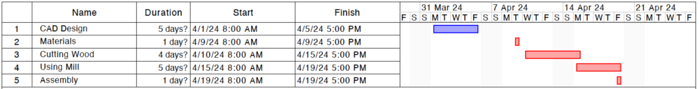
Fabrication Process
As previously shown in the timeline, the fabrication process consisted of multiple steps that led to the cheese press being made. Below are detailed descriptions to each step in the process.
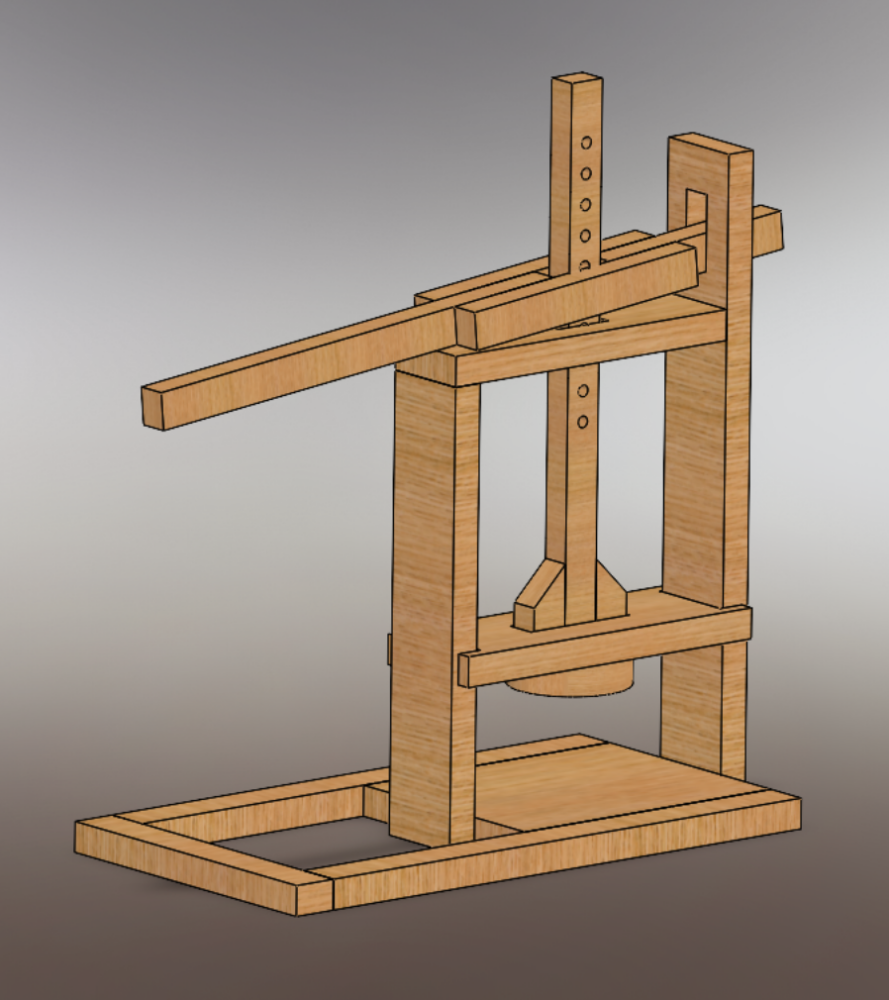
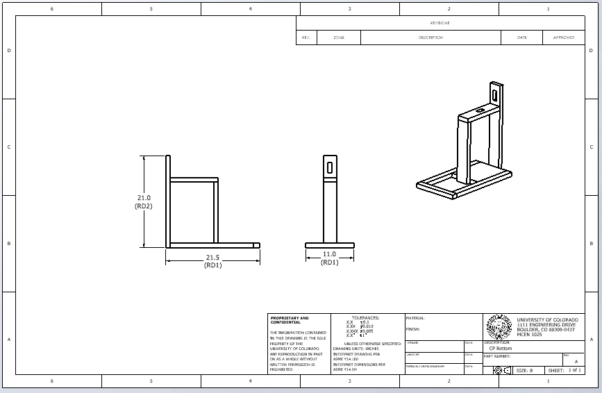
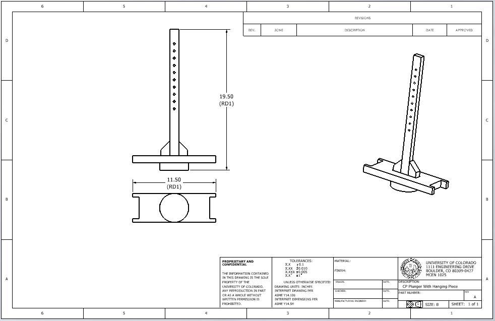
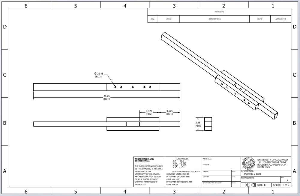
Initial CAD design:
The cheese press was designed based off of a design on how to make a Dutch-style cheese press that was produced by the YouTube channel “Ozark Mountain Goats”. The main assembly was split in to three separate assemblies.
Calculation of Wood Needed:
After the CAD files were made, an excel spreadsheet was created to track the length and width of each component piece in the full assembly. To make it easier to examine, the list on the excel spreadsheet was split up by sub assemblies.
Some of the parts that exist in the assembly were identical, so the quantity of each part was taken into consideration, To better organize this information, a second table was created that grouped each width separately, added the lengths of each part with the same length, and created a running total for how long of pieces of wood were needed for each width. Not all of the specific sizes that were needed for the cheese press were stock sizes, so in consideration of each width, the stock size closest to the width needed for the assembly was written down. Another column was made to consider the lengths of each cut needed in increasing order of size.
The price of each pieces was kept track of, so the project would remain under the $150 budget cap. Tax was not considered in the original cost estimate, but the total price of these pieces without tax came out be $58.42.
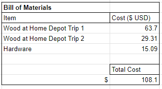
Materials Acquisition
The required wood that was calculated in the previous section was purchased at Home Depot. Two different trips to Home Depot were made. On the first trip, the amount of wood calculated in the previous section was purchased. The total cost was $63.70.
After some wood cutting trial and error, more wood was needed so that certain pieces could be remade. The total cost for wood at the second trip to Home Depot was $29.31.
Also purchased were 4: 1/4-20 x 3″ hex head bolts, 4: 1/4-20 wing nuts, 3 packs of #8 x 1 1/2 wood screws, and a pack of multipurpose sandpaper. These items together cost $15.09.
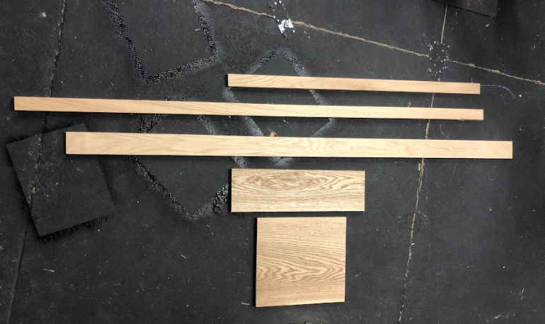
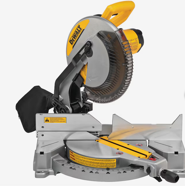
Cutting wood to proper dimensions
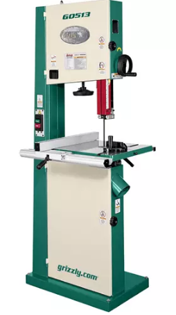
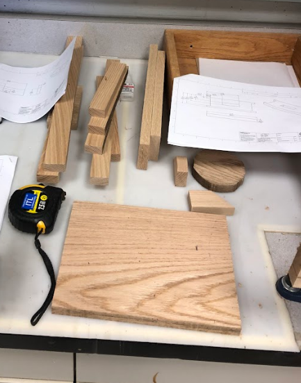
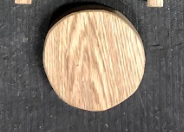
Once the purchase of wood was made, the wood was taken to the ITLL’s Manufacturing Center Wood Shop so it could be cut into the dimensions needed. A table saw was used to cut the pieces to their appropriate lengths. Some of the pieces were too wide to be cut with the table saw, such as the 8″ x 10″ base plate. Other pieces had to be slimmed down after being cut with the table saw. These pieces were then cut with a band saw. A band saw was also used to cut the circle pieces that is part of the vertical press sub-assembly.
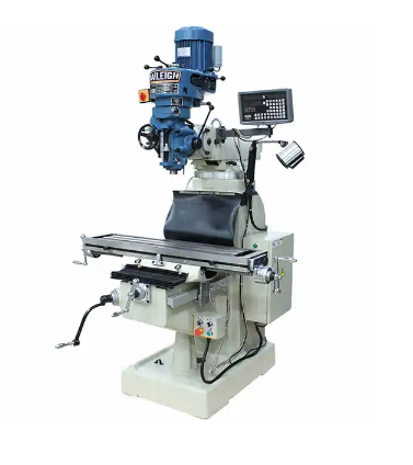
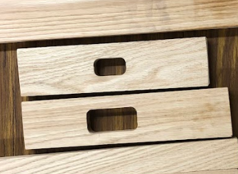
Shaping and Milling the Wood
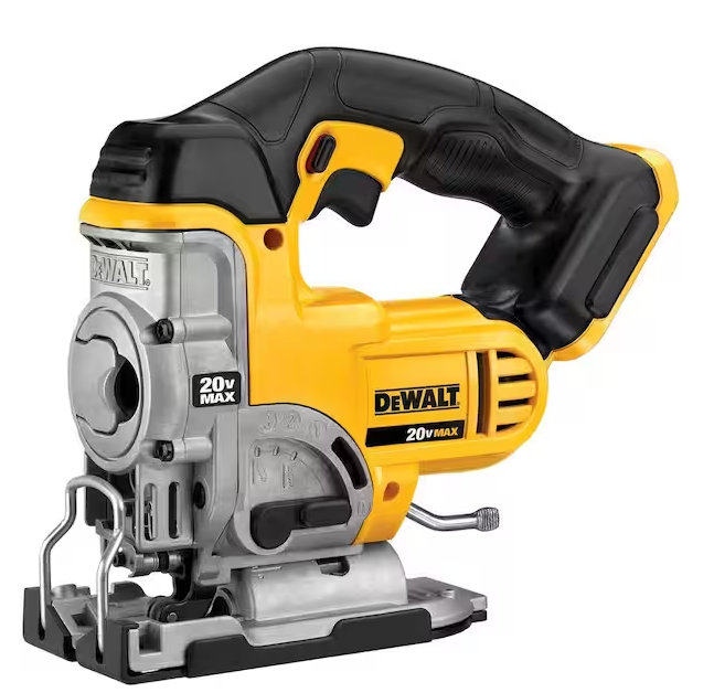
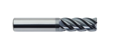
The wood was sanded on all of the edges to give them a more round appearance. There were three slots that had to be cut into three separate pieces of wood. This process proved to have its challenges. After talking about different processes with Jenn from the ITLL manufacturing center she said I could try two different processes. One was to make 4 pilot holes that form a rectangle and then to use a jigsaw to cut out each slot. The second style was to use an end mill on the manual mill to take out the material from the wood. The former approach sounded like it would be the faster of the two, so it was attempted first. An outline was drawn for where each slot was desired. There was some trouble using the jigsaw on such small pieces and the slots ended up being uneven.
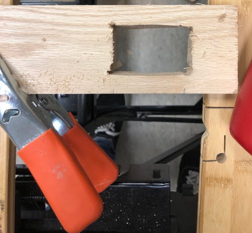
I tried to reshape these using a hand file, but was not impressed with the look. I decided to take the end mill approach instead. With the end mill bit, two passes with the manual mill at full depth to remove material. I was much more happy with the outcome from this process.
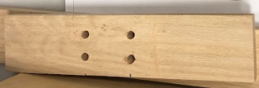
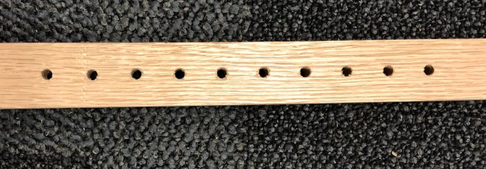
After these slots were made, the manual mill was also used to drill out evenly spaced holes for the press arm to be connected to the vertical press component.
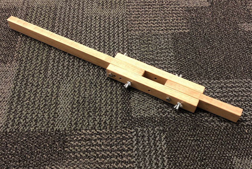
Assembly
There were two separate steps to the final assembly. The press arm was assembled using the bolts and wing nuts previously mentioned in the materials acquisition section.
After the press arm was put together, the body was connected using wood screws. This ended up being more challenging than previously though. The pilot holes that were originally made were too small for the wood screws and several screws sheared in the process of drilling while using a hand drill.
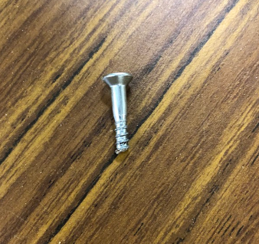
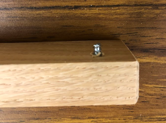
A larger pilot hole of 1/8″ for the #8 screw (which is 5/32″) was chosen and the screws were able to be placed in the wooden pieces. It was difficult to hold the wooden pieces together, which lead to some unevenness in the final assembly.
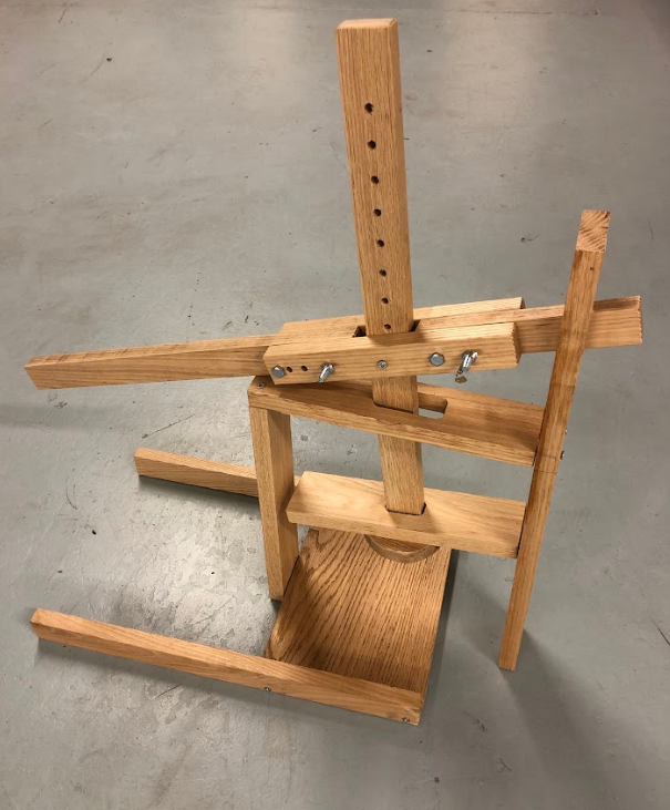
Conclusion
The final cheese press made had a lot of similarities to the starting point. The craftsman aesthetic was reached, but the shape ended up being different. The main differences being how the bottom section looks. Originally The base piece was going to be completely connected, but after having difficulties screwing the wooden pieces together, a more open design was chosen. Also, a design was going to be made on the wooden pieces using a wood burning tool, but there was not enough time to do that before the presentation.
The main thing that would be done differently is to use less bolts and instead have the wooden pieces fit in to each other for support. I would like to have them fit into each other with a press fit that would only require the pieces to be hit together somewhat softly with a mallet. I plan on redesigning this and remaking it in this style over the summer.
2 Comments. Leave new
[…] Post 12: Final Report Part 2: How […]
Hey Ben, this project is really cool! If you were to do it again what do you think you would change about it?