
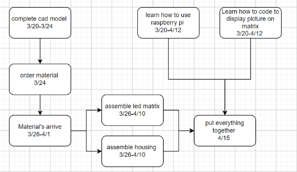
- Starting on the twentieth of March I finished finalizing my CAD model and ordered all my materials, my materials being wood, LEDs, and cables. I also ordered a raspberry pi and soem things to make soldering eaiser.
- Simultaneously I learned how to code on a controller for the panel.I used a Raspberry Pi as the controller. As this was a very large part of the project im left the majority of the project in this part of the timeline. I allocated from March third to April twelfth for coding.
- For assembling the housing im allocated around 16-20 days because this part of the project doesn’t have to be done until the LED panel is finished. This is just the wood that is holding the LED panel.
- Im also left a similar time frame for assembling the LED panel as this will take longer than the housing itself
- The rest of the time was spent making the code run better and adding the final touches.
Fabrication process
- Frame
- For the frame I used the wood shop in the ITL to cut the wood into 2 pieces of 8.75in x 2.95 in and 2 pieces of 3.75in x 2.95 in. I then used screws to assemble the frame being careful about splitting the wood by using pilot holes. After this, I press-fit the led matrix into the frame. Unfortunately, I did split the wood in one of the back corners it is however not noticeable and I plan on replacing this piece of wood late
- LED matrix
- Following Pat in the idea forge advice, I bought a kit from Adafruit for the matrix. This kit included everything I needed to make the matrix itself but did not include things like the Raspberry Pi or some of the cables I needed.
- code
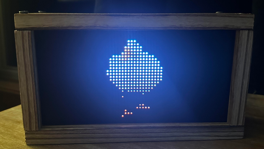
- Thanks to Henner Zeller on GitHub I was able to understand and make a code that works for animations and pictures. I plan on looking into making notifications and a clock work too. (https://github.com/hzeller/rpi-rgb-led-matrix)
Conclusion
- Im very happy with how this project turned out. It fits perfectly on my desk and seamlessly fits into my set up. I cna customize it to be however i want it to be and iu think it looks great. When i started the project i initially wanted to use an arudino because that was what i was comfortable with. Im really happy that in the end i used a raspberry pi because it was a new thing for me to learn, it is totally different than an arduino. Going forward i want to make the back panel with custom inputs for preloaded pictures, integrating a battery so it can be seamless, and add charging. Again im very happy with the final product.
Small video